Fpga Circuit Diagram Ripple Carry Adder
Fpga implementation of adders: (a) 4-bit adder stage and (b) output Adder carry why bit simply stack because does light just but Ripple carry adder in vhdl and verilog
intel fpga - Why is carry on for an adder that is simply on
Ultimate guide: fpga programming Fpga implementation circuit adder adders Adder ripple sipo converter fpga
Adder carry ripple bit four library circuit lpm alus lab
Schematic of a 32 bit ripple carry adder.Intel fpga Adder carry ripple verilog code bit using following structural modelingAdder ripple carry electronics digital.
Fpga programming adderRipple carry adder Carry ripple adder multisimInf2c-cs lab 2: systemc basics.
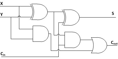
Block diagram of 4-bit ripple carry adder
Digital electronics-projects-circuits-tutorials-basics-books-designRipple adder Lab2 de2 board carry ripple adder circuit figureAdder ripple carry bit vhdl diagram block verilog module.
Fpga implementation of adders: (a) 4-bit adder stage and (b) outputAdder bit ripple carry schematic fa lab ac cs code makefile courses labs inf teaching ed Verilog code for ripple carry adderFpga adders adder implementation complement.


